
Page 205 - Engineering drawing from first principles using AutoCAD
P. 205
198 Engineering drawinq [rom [irst principles
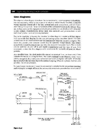
Line diagrams
The object of a line diagram is to show the connections in a system to prove its feasibility,
but not necessarily wired in the manner in which it will be finally installed. Complete
wiring diagrams contain all of the line, neutral and earth connections, and are drawn
after taking into account the actual positions of the component parts in the system. They
are, in fact, drawn as the equipment is built and possibly include details of wire sizes and
colour codings. Manufacturers devise their own methods and presentations to suit
individual products and service requirements.
Due to its simplicity in layout, the circuitry in a line diagram is easier to follow. Figure
9.12 shows the line diagram for the central heating system described above. The time
control consists of a clock which must run continuously while the circuit is energised. The
timer also contains two switches which may be operated independently. One switch
controls the central heating circuit, the other the domestic hot water circuit. The controls
can be switched on and off to suit family requirements and the time of year. It is
customary to draw the line diagram with switches in the normally off position where
possible.
At a specified time, the clock makes the contact to terminal 3 on the timer and, if the
cylinder thermostat is calling for heat, the brown terminal on the domestic water valve
will be energised. Both valves are motorised and when energised will open. When the
line is switched off,they close due to the action of a spring. When the cylinderthermostat is
satisfied, the circuit is broken.
In many homes the domestic water is automatically switched to the on position morning
and evening for a couple of hours, but an override switch also provides hot water control
HTS3 CYLSTAT
1---------, DHWVALVE
ILP112 TIMER DRAYTON ZV28
r-----, 1 2(SAT) I ,---------,
31 (HWON) 1(COM) • I
• I @ I , ~ • 1 , ® ' BROWN. M BLUE I
.1 1 (OFF) 1 CALL I 1
I L ________ -J I GREY I
1 ,ORANGE
I
1 ~-----1
1
,
1 RTS1 ROOM STAT
I 1--------, CHVALVE
I , I DRAYTON ZV28
1
4 (CH ON) 1 L e __ N I ,---------,
• I ® I I I BROWN M BLUE I
1 I
.21 (OFF) I 3 I , GREY 1
I L _______ -.J 1ORANGE 7
WHIT
L, 6 I L~ _______ -.J
1
N'
MAINS
SUPPLY .........--------t14.---------------------I----n
CENTRAL HEATING WIRING 3
LINE DIAGRAM
L N E
SUPPLY TO
BOILER & PUMP
Figure 9.12