
Page 210 - Engineering drawing from first principles using AutoCAD
P. 210
Technical drawinqs for industry 203
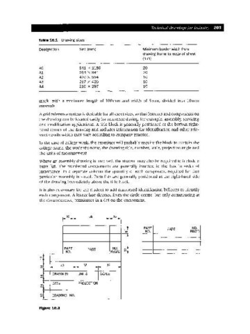
Table 10.1 Drawing sizes
Designation Size (mm) Minimum border width from
drawing frame to edge of sheet
(mm)
AO 841 x 1189 20
A1 594 x 841 20
A2 420 x 594 10
A3 297 x 420 10
A4 210 x 297 10
mark, with a minimum length of lOOmm and width of Smm, divided into lOmm
intervals.
A grid reference system is desirable for all sheet sizes, so that features and components on
the drawing can be located easily for reference during, for example, assembly, servicing
and modification applications. A title block is generally positioned at the bottom right-
hand corner of the drawing and includes information for identification and other rele-
vant details which may vary according to company practice.
In the case of college work, the examiner will probably require the block to contain the
college name, the student's name, the drawing title, number, scale, projection angle and
the units of measurement.
Where an assembly drawing is involved, the student may also be required to include a
parts list. The numbered components are generally inserted in the box in order of
importance. In a separate column the quantity of each component required for that
particular assembly is stated. Parts lists are generally positioned at the right-hand side
of the drawing immediately above the title block.
It is also customary for the student to add numbered identification balloons to identify
each component. A leader line directed from the circle centre, but only commencing at
the circumference, terminates in a dot on the component.
16 55 16
I
I
PART PART NO.
NO. REQ'D
PART PART NO.
NO. REQ'D
~
"
r -- 40 - - 32 32 -
DRAWN BY UNITS SCALE
,r
~ DATE PROJECTION
r
l
C\I
...- DRAWING NO.
Figure 10.3