
Page 214 - Engineering drawing from first principles using AutoCAD
P. 214
Technical drawinqs for industry 207
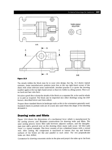
THIRD ANGLE
SOLUTION
A-A
A
L
l.-s
B-B
Figure 10.8
The details within the block may be to your own design, but Fig. 10.3 shows typical
contents. Some manufacturers position parts lists at the top right-hand corner of the
sheet with other relevant notes underneath. Another practice is to quote the drawing
number again at the top right-hand corner so that it is visible in a filing system. There are
no hard and fast rules here.
It is also a good idea to keep the details of the block on a separate file, to be used in whole
or in part as required. The block can be imported into other drawings using the DXF
feature, described below and then edited.
Prepare these standard sheets in landscape style as this is the orientation generally used.
Standard sheets in portrait style are of course also used when the shape of the drawing
demands it.
Drawing webs and fillets
Figure 10.4 shows the dimensions of a mechanical lever which is manufactured by
the casting process, and illustrates constructions for drawing webs and fillets. The
sand casting process leaves fillet radii between adjacent surfaces, and the draughts-
man may add a general note on the drawing when many radii occur: 'All fillet radii
Smm' is a typical example. This lever consists of two cylindrical bosses with a central
web. After casting, the component is machined to ensure that top and bottom
surfaces of the bosses are flat and parallel to each other. The two perpendicular
holes are then drilled.
Commence by drawing concentric circles in the plan and project the sides up to the front