
Page 216 - Engineering drawing from first principles using AutoCAD
P. 216
Techn ical drawinqs for industry 209
view. Add horizontal construction lines to establish the thicknesses of each of the cylind-
rical parts and the web. Remember to use the ORTHO and SNAP modes whenever
possible.
The next stage is to draw tangents to the outside diameters of the bosses and determine
the tangency points. AutoCAD conveniently provides OBJECT SNAPmodes in the tool-
box. Choose the TANGENT button in the toolbox. Follow the instruction at the command
line to snap on one of the circles, then the other, and the tangent will be automatically
drawn. We now need to establish the exact points of tangency (A and B) at each end of
the tangent line (Fig. 10.5).
To position point A, choose the Line button in the toolbox. Then choose the Centre
button in the toolbox and the cursor will change in appearance to a target box. Choose
the Circle button, click on the circle, and the starting point for the line snaps to the circle
centre.
Choose the Perpendicular button and click on the tangent on your drawing; a line will
be drawn to the exact position. Now we need to project a vertical line up to the front view,
and this will be perpendicular to the top face of the boss. Choose the Perpendicular
button again and click on the face of the boss to give the point X.Repeat the procedure for
points Band Y.
Youwill note on the front view that two 90° fillets are drawn at the centre of the web, but
I
-+-
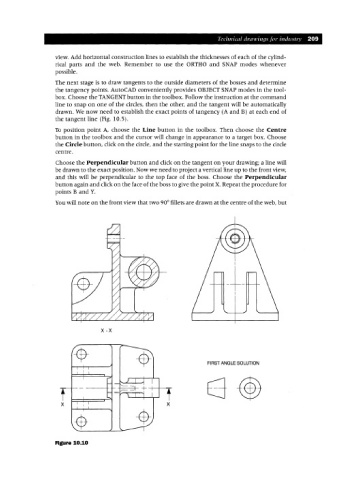
x-x
FIRST ANGLE SOLUTION
x
Figure 10.10