
Page 217 - Engineering drawing from first principles using AutoCAD
P. 217
210 Engineering drawing [rom first principles
at the tangency points, where the projection of the fillet radii terminates, it is the custom
to draw only a 45° fillet. Use the FILLET command to insert the four fillets. At each
tangency point draw short 45° lines and with the BREAI( command erase the unwanted
portion. Extend the lines with the STRETCH command.
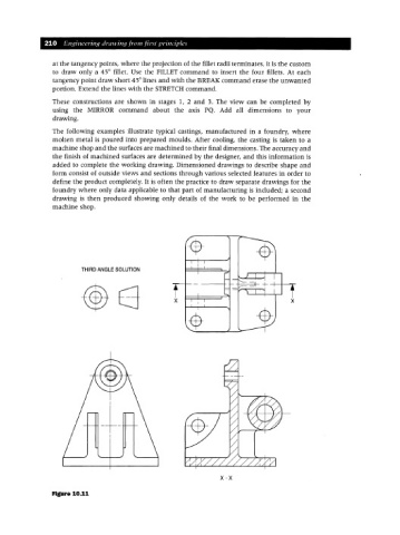
These constructions are shown in stages 1, 2 and 3. The view can be completed by
using the MIRROR command about the axis PQ. Add all dimensions to your
drawing.
The following examples illustrate typical castings, manufactured in a foundry, where
molten metal is poured into prepared moulds. After cooling, the casting is taken to a
machine shop and the surfaces are machined to their final dimensions. The accuracy and
the finish of machined surfaces are determined by the designer, and this information is
added to complete the working drawing. Dimensioned drawings to describe shape and
form consist of outside views and sections through various selected features in order to
define the product completely. It is often the practice to draw separate drawings for the
foundry where only data applicable to that part of manufacturing is included; a second
drawing is then produced showing only details of the work to be performed in the
machine shop.
THIRD ANGLE SOLUTION
x x
-+-
x-x
Figure 10.11