
Page 206 - Engineering drawing from first principles using AutoCAD
P. 206
Blocks and technical diaqrams 199
ILP112 TIMER
1- - - - - - - - - - - - - - I
I I
I I
I I
~ L 4 ~
WIRING CONNECTIONS
ROOM STAT CYLSTAT
1--------, ,---------,
I N I
I I : (COM) ~:
I L I I
I 3 I I CALL I
I I I I
L__ _..J L .J
r-- ---I
I I
I 2 I
I I
I L N E I
I SUPPLY TO I
I BOILER &PUMP MAINS I
I SUPPLY N I
E
I I
I I
L _ _-.J
1---------, ,---------,
I BROWN M BLUE I : BROWN. M BLUE I
I GREY I I GREY [
,ORANGE I ORANGE
I W-·H_.I_T---L---_-..l I WHrT
L ~ L~ -.J
DHWVALVE CHVALVE
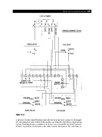
Figure 9.13
at all times. On the central heating circuit, the line from the timer contact 4 will energise
the valve and allow water to flow to the radiators, provided the room thermostat is calling
for heat. Note that the grey terminals on both valves are connected to terminal 7 because,
if heat is required for either system, the boiler must be switched on. Note also that the