
Page 202 - Engineering drawing from first principles using AutoCAD
P. 202
Blocks and technical diaqrams 195
QJ
'--~ ~21 ~_~
I~-Il
I I I
I I I
I CONTROL I I
I VALVE I I
I I I
I ~ I
I I
4 DJ I
pUMP LRV RADIATOR
I
I
I
L __ - o
5 BALANCING
BOILER VALVE
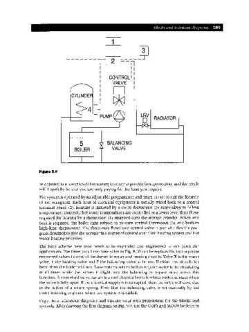
Figure 9.9
be adjusted to a lower level if necessary in order to provide frost protection, and the result
will hopefully be that you are only paying for the heat you require.
The system is operated by an adjustable programmer and timer (1) set to suit the lifestyle
of the occupants. Each item of electrical equipment is usually wired back to a central
terminal board (2). Heating is initiated by a room thermostat (3) responding to falling
temperature. Domestic hot water temperatures are controlled at a lower level than those
required for heating by a thermostat (4) strapped onto the storage cylinder. When any
heat is required, the boiler runs subject to its own control thermostat (5) and built-in
high-limit thermostats. The three-way flowshare control valve is part of a flexible pro-
gram designed to give the occupants a degree of control over their heating system and hot
water heating priorities.
The basic scheme here now needs to be expanded and engineered to suit particular
applications. The three-way flowshare valve in Fig. 9.10 can be replaced by two separate
motorised valves to control the domestic water and heating circuits. Valve X is the water
valve, Y the heating valve and Z the balancing valve as before. If either circuit calls for
heat, then the boiler will run. Low-water-content boilers require water to be circulating
at all times while the burner is alight, and the balancing or bypass valve serves this
function. A motorised valve has an internal electrical switch which makes contact when
the valve is fully open. If the electrical supply is interrupted, then the valve will close due
to the action of a return spring. Note that the balancing valve is set manually by the
commissioning engineer when the system is installed.
Copy these schematic diagrams and assume your own proportions for the blocks and
symbols. After drawing the first diagram on Fig. 9.9, use the COpy and MOVE facilities to