
Page 197 - Engineering drawing from first principles using AutoCAD
P. 197
190 Engineering drawinq [rom first principles
Pick the Select Objects box. Draw a box around the valve and press <Enter>. Note that
the number found in the Block Definition box changes (in this case) to 15. If you wish
to check that the block has been successfully made enter Block at the command line then
? and a list of defined blocks will appear.
To define and write the block to disc type WBLOCK at the command line or select the
Import/Export option in the File menu. Click on Block Out. The Create Drawing File
dialogue box appears shown in Fig. 9.3. Enter the symbol name SVT3 and choose OK.
The block now has its own drawing file number. The command line asks for the Block
name. Enter SVT3. Repeat this procedure for the other valve by saving your drawing
under a new file name and change the number to SVT4. Make the second block as before.
A typical application follows in Fig. 9.4 where part of a piping layout is shown and it is
necessary to position accurately two valves of each type. The co-ordinates for valve SVT3
are X=80, Y=140 and X=130, Y=40, and those for valve SVT4are X=230, Y=140 and
X = 190, Y = 90.
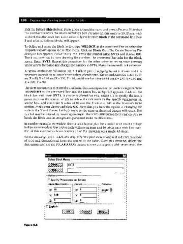
The next operation is to insert the symbol in the correct position on the line diagram. Type
DDINSERT at the command line and the Insert box in Fig. 9.5 appears. Click on the
block box and insert SVT3. A choice is offered for you, either (1) to specify the insert
parameters on the screen, or (2) to delete the tick mark in the Specify Parameters on
screen box, and insert the X value of 80 and the Y value of 140 in the Insertion Point
section. Make your choice and click OK. Note that you have the option of changing the
scale in the X and Yaxes, but both must be the same or distorted images will result. The
symbol may be rotated by inserting an angle. The EXPLODE button here enables you to
break the block into its component parts and make modifications.
In another example we wish to draw a table layout plan for a social function at a village
hall to accommodate four tables each with seven seats and 10 tables each with five seats.
Part of this exercise is also to prepare all of the drawings on a single A3 sheet.
Set the drawings limits to 420,297 (Fig. 9.7). The plan view of one seat is drawn to a scale
of 1:10 and dimensioned from the centre of the table. Copy this drawing, delete the
dimensions and use the POLARARRAY feature to construct a group with seven seats. The
Insert •
r Select BlockNai:~~------"---~--·~--_·---~,~-.-.-..- ··~----I· I
..
11:!!i:li!lil!II[!III~~:~ IIIIII!II Ir-----------_II.
•__"'!:=:=..=.=.===========::::::====_.:.-->.
~_~. ....__•__..... ._.... • m
Figure 9.5