
Page 200 - Engineering drawing from first principles using AutoCAD
P. 200
Blocks and technical diaqrams 193
Midi sequencer application
It is often necessary to write clear instructions and produce understandable diagrams
where products are interconnected, for the benefit of users. Hi-fi and computer con-
trolled equipment are typical examples where several expensive components need to be
wired together. All-embracing universal diagrams are sometimes confusing when they
are not up-to-date or contain models of equipment slightly different to those you happen
to have purchased. A diagram should therefore be accurate, clear, relevant, unambiguous
and in good proportion.
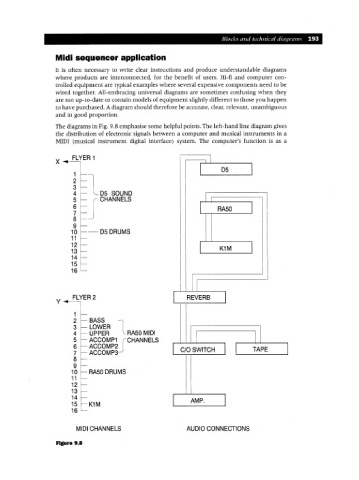
The diagrams in Fig. 9.8 emphasise some helpful points. The left-hand line diagram gives
the distribution of electronic signals between a computer and musical instruments in a
MIDI (musical instrument digital interface) system. The computer's function is as a
FLYER 1
X I
1 I D5 I
2
3
4 -los SOUND
5 CHANNELS
6 I RA50 I
7
8
9
10 -D5DRUMS
11
12 I I
13 K1M
14
15
16
II
FLYER 2 I REVERB I
Y
1
2 BASS -)
3 LOWER I
4 UPPER '-- RA50 MIDI
5 ACCOMP1 Jf CHANNELS I II
6 ACCOMP2 I I I TAPE I
7 ACCOMP3- C/O SWITCH
8
9
10 RA50 DRUMS
11
12
13
14
15 K1M AMP.
16
MIDI CHANNELS AUDIO CONNECTIONS
Figure 9.8