
Page 262 - Engineering drawing from first principles using AutoCAD
P. 262
Technical drawinqs for industry 255
R6
- -1- -
(0 co co
co to N -+- B
lSl lSl tS)
- -I--
I
I
I
-+--
i J
I.. 24
6 30 6
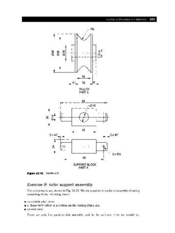
PULLEY
PART 2
80
I... 42
] ..
2 X 45° 2 x 45°
1 I I
I I I
1 I I
-~-+-+---
1 I 1
I
I 1
1 I I
I 2x03
i.. 68 .1
SUPPORT BLOCK
PART 4
Figure 10.41 (continued)
Exercise 9: roller support assembly
The components are shown in Fig. 10.37. We are required to make an assembly drawing
consisting of the following views:
• an outside plan view;
• a front view taken as a section on the cutting plane AA;
• an end view.
There are only five parts to this assembly, and in the sectional view we would not