
Page 263 - Engineering drawing from first principles using AutoCAD
P. 263
256 Engineering drawinq [rom first principles
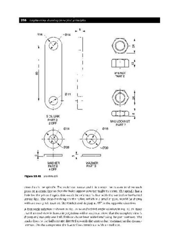
R14 014
o M16 NUT
(J)
PART 6
014
(r!lJ~
SIDE LINK
PART 3 M16 LOCKNUT
20FF
PART?
WASHER WASHER
PART 8 PART 9
40FF
Figure 10.41 (continued)
cross-hatch the spindle. The roller can rotate and it is always the custom to show such
parts on a centre line so that the holes appear symmetrically in views. The spindle has a
hole for the pin and again this would be oriented in line with the vertical or horizontal
centre line. The cross-hatching on the roller, which is a smaller part, would be drawn
with a closer pitch than on the bracket and sloping at 45° in the opposite direction.
A first angle solution is shown in Fig. 10.38 and a third angle solution in Fig. 10.39. Note
that if an end view is drawn in projection with a sectional view, that the complete view is
drawn and not only one half. Balloons have been added enclosing the part numbers. The
leader lines to the balloons are directed towards the centres but terminate at the circum-
ference. On the component the leader lines terminate with a small dot.