
Page 75 - Engineering drawing from first principles using AutoCAD
P. 75
Chapter ~
Pictorial projections
This chapter introduces the following topics:
• Isometric principles and planes.
• Oblique, Cavalier and Cabinet projections.
• Planometric projections.
• COpy and ROTATE features applied to animation.
Isometric and oblique projections
Isometric and oblique projections are the most common methods of drawing and sketch-
ing, so that the three-dimensional proportions of a component can be seen in one illustra-
tion. These forms of projection do not take into account the element of perspective which
a true artist produces. Their function is to convey understandable shape and form and
instant recognition. The ability to read two-dimensional drawings and plans requires some
study and appreciation of their construction in order to interpret the linework. If you
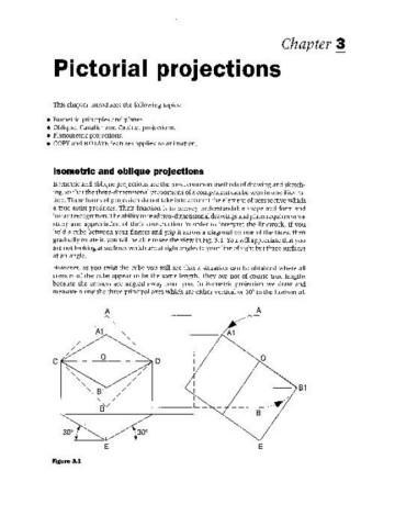
hold a cube between your fingers and grip it across a diagonal on one of the faces, then
gradually rotate it, you will be able to see the view in Fig. 3.1. You will appreciate that you
are not looking at surfaces which are at right angles to your line of sight but three surfaces
at an angle.
However, as you twist the cube you will see that a situation can be obtained where all
corners of the cube appear to be the same length. They are not of course true lengths
because the corners are angled away from you. In isometric projection we draw and
measure along the three principal axes which are either vertical or 30° to the horizontal.
A A
I-----~
/ -, I
//A1 -, -, I A1
/ -, 1
/ -,
/ -, 1
/ ~ I
C °1 D f---" ------
-, / 1
-, /
-, /
-, / I
-, 81
",81 / I
-, / 1
8/ L_
E E
Figure 3.1