
Page 84 - Engineering drawing from first principles using AutoCAD
P. 84
Pictorial projections 77
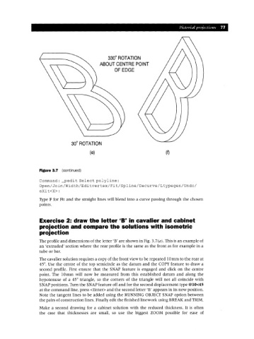
330 ROTATION
0
ABOUT CENTRE POINT
OF EDGE
0
30 ROTATION
(e) (1)
Figure 3.7 (continued)
Command: _pedi t Select polyline:
Open/Join/Width/Editvertex/Fit/Spline/Decurve/Ltypegen/Undo/
eXit<X>:
Type F for Fit and the straight lines will blend into a curve passing through the chosen
points.
Exercise 2: draw the letter 'B' in cavalier and cabinet
projection and compare the solutions with isometric
projection
The profile and dimensions of the letter 'B' are shown in Fig. 3.7(a). This is an example of
an 'extruded' section where the rear profile is the same as the front as for example in a
tube or bar.
The cavalier solution requires a copy of the front view to be repeated lOmm to the rear at
45°. Use the centre of the top semicircle as the datum and the COpy feature to draw a
second profile. First ensure that the SNAP feature is engaged and click on the centre
point. The 10mm will now be measured from this established datum and along the
hypotenuse of a 45° triangle, so the corners of the triangle will not all coincide with
SNAPpositions. Turn the SNAPfeature off and for the second displacement type @lO<45
at the command line, press <Enter> and the second letter 'B' appears in its new position.
Note the tangent lines to be added using the RUNNING OBJECT SNAP option between
the pairs of construction lines. Finally edit the finished linework using BREAI< and TRIM.
Make a second drawing for a cabinet solution with the reduced thickness. It is often
the case that thicknesses are small, so use the biggest ZOOM possible for ease of