
Page 87 - Engineering drawing from first principles using AutoCAD
P. 87
80 Engineering drawinq [rom first principles
I
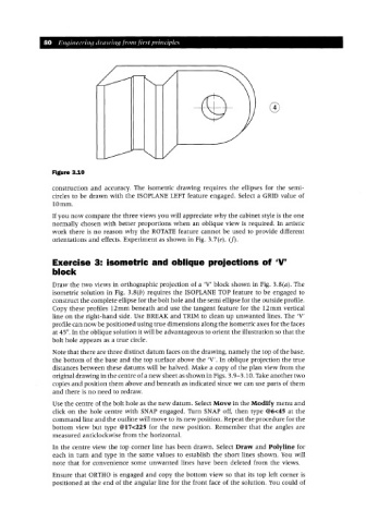
Figure 3.10
construction and accuracy. The isometric drawing requires the ellipses for the semi-
circles to be drawn with the ISOPLANE LEFT feature engaged. Select a GRID value of
l Ornm.
If you now compare the three views you will appreciate why the cabinet style is the one
normally chosen with better proportions when an oblique view is required. In artistic
work there is no reason why the ROTATE feature cannot be used to provide different
orientations and effects. Experiment as shown in Fig. 3.7(e), (f).
Exercise 3: isometric and oblique projections of 'V'
block
Draw the two views in orthographic projection of a 'V' block shown in Fig. 3.8(a). The
isometric solution in Fig. 3.8(b) requires the ISOPLANE TOP feature to be engaged to
construct the complete ellipse for the bolt hole and the semi ellipse for the outside profile.
Copy these profiles 12mm beneath and use the tangent feature for the 12mm vertical
line on the right-hand side. Use BREAI( and TRIM to clean up unwanted lines. The 'V'
profile can now be positioned using true dimensions along the isometric axes for the faces
at 45°. In the oblique solution it will be advantageous to orient the illustration so that the
bolt hole appears as a true circle.
Note that there are three distinct datum faces on the drawing, namely the top of the base,
the bottom of the base and the top surface above the 'V'. In oblique projection the true
distances between these datums will be halved. Make a copy of the plan view from the
original drawing in the centre of a new sheet as shown in Figs. 3.9-3.10. Take another two
copies and position them above and beneath as indicated since we can use parts of them
and there is no need to redraw.
Use the centre of the bolt hole as the new datum. Select Move in the Modify menu and
click on the hole centre with SNAP engaged. Turn SNAP off, then type @6<45 at the
command line and the outline will move to its new position. Repeat the procedure for the
bottom view but type @17<225 for the new position. Remember that the angles are
measured anticlockwise from the horizontal.
In the centre view the top corner line has been drawn. Select Draw and Polyline for
each in turn and type in the same values to establish the short lines shown. You will
note that for convenience some unwanted lines have been deleted from the views.
Ensure that ORTHO is engaged and copy the bottom view so that its top left corner is
positioned at the end of the angular line for the front face of the solution. You could of