
Page 87 - Entrophy Analysis in Thermal Engineering Systems
P. 87
Endoreversible heat engines 79
The maximum power output of the cycle is obtained by substituting
Eq. (6.29) into Eq. (6.28).
_ _
p ffiffiffiffiffiffiffiffiffi p ffiffiffiffiffiffiffiffi 2
C h C l
_ W max ¼ T h,in (6.30)
_ _ T l,in
C h + C l
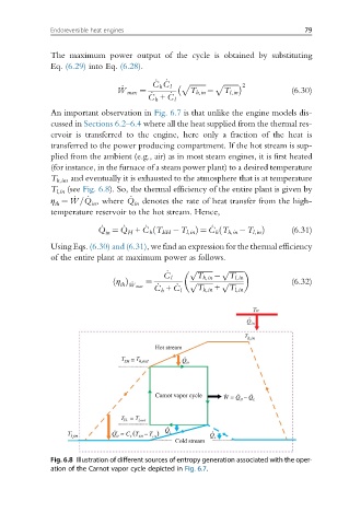
An important observation in Fig. 6.7 is that unlike the engine models dis-
cussed in Sections 6.2–6.4 where all the heat supplied from the thermal res-
ervoir is transferred to the engine, here only a fraction of the heat is
transferred to the power producing compartment. If the hot stream is sup-
plied from the ambient (e.g., air) as in most steam engines, it is first heated
(for instance, in the furnace of a steam power plant) to a desired temperature
T h,in , and eventually it is exhausted to the atmosphere that is at temperature
T l,in (see Fig. 6.8). So, the thermal efficiency of the entire plant is given by
_
_
η ¼ _ W =Q , where Q denotes the rate of heat transfer from the high-
th in in
temperature reservoir to the hot stream. Hence,
_ _ _ _
ð
ð
Q ¼ Q + C h T EH T l,in Þ ¼ C h T h,in T l,in Þ (6.31)
in H
Using Eqs. (6.30) and (6.31), we find an expression for the thermal efficiency
of the entire plant at maximum power as follows.
_ p ffiffiffiffiffiffiffiffiffi p ffiffiffiffiffiffiffiffi
ffiffiffiffiffiffiffiffiffi p
η ð Þ _ ¼ C l p T h,in T l,in (6.32)
_ _ T h,in + T l,in
ffiffiffiffiffiffiffiffi
th W max
C h + C l
Fig. 6.8 Illustration of different sources of entropy generation associated with the oper-
ation of the Carnot vapor cycle depicted in Fig. 6.7.