
Page 129 - Facility Piping Systems Handbook for Industrial, Commercial, and Healthcare Facilities
P. 129
PIPING
PIPING 2.79
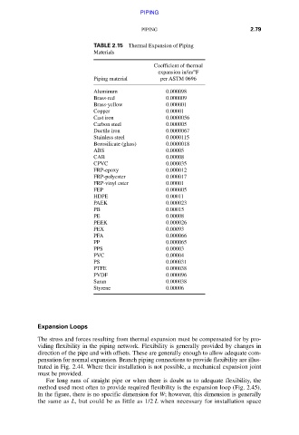
TABLE 2.15 Thermal Expansion of Piping
Materials
Coefficient of thermal
expansion in/in/°F
Piping material per ASTM 0696
Aluminum 0.000098
Brass-red 0.000009
Brass-yellow 0.000001
Copper 0.00001
Cast iron 0.0000056
Carbon steel 0.000005
Ductile iron 0.0000067
Stainless steel 0.0000115
Borosilicate (glass) 0.0000018
ABS 0.00005
CAB 0.00008
CPVC 0.000035
FRP-epoxy 0.000012
FRP-polyester 0.000017
FRP-vinyl ester 0.00001
FEP 0.000005
HDPE 0.00011
PAEK 0.000023
PB 0.00015
PE 0.00008
PEEK 0.000026
PEX 0.00093
PFA 0.000066
PP 0.000065
PPS 0.00003
PVC 0.00004
PS 0.000031
PTFE 0.000038
PVDF 0.000096
Saran 0.000038
Styrene 0.00006
Expansion Loops
The stress and forces resulting from thermal expansion must be compensated for by pro-
viding flexibility in the piping network. Flexibility is generally provided by changes in
direction of the pipe and with offsets. These are generally enough to allow adequate com-
pensation for normal expansion. Branch piping connections to provide flexibility are illus-
trated in Fig. 2.44. Where their installation is not possible, a mechanical expansion joint
must be provided.
For long runs of straight pipe or when there is doubt as to adequate flexibility, the
method used most often to provide required flexibility is the expansion loop (Fig. 2.45).
In the figure, there is no specific dimension for W; however, this dimension is generally
the same as L, but could be as little as 1/2 L when necessary for installation space
Downloaded from Digital Engineering Library @ McGraw-Hill (www.accessengineeringlibrary.com)
Copyright © 2009 The McGraw-Hill Companies. All rights reserved.
Any use is subject to the Terms of Use as given at the website.