
Page 130 - Facility Piping Systems Handbook for Industrial, Commercial, and Healthcare Facilities
P. 130
PIPING
2.80 CHAPTER TWO
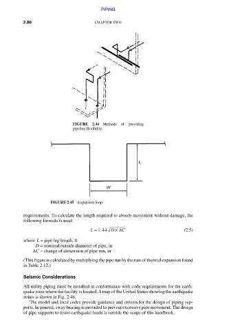
FIGURE 2.44 Methods of providing
pipeline flexibility.
FIGURE 2.45 Expansion loop.
requirements. To calculate the length required to absorb movement without damage, the
following formula is used:
.
L = 144 D × Δ C (2.5)
where L = pipe leg length, ft
D = nominal outside diameter of pipe, in
ΔC = change of dimension of pipe run, in
(This figure is calculated by multiplying the pipe run by the rate of thermal expansion found
in Table 2.12.)
Seismic Considerations
All utility piping must be installed in conformance with code requirements for the earth-
quake zone where the facility is located. A map of the United States showing the earthquake
zones is shown in Fig. 2.46.
The model and local codes provide guidance and criteria for the design of piping sup-
ports. In general, sway bracing is provided to prevent excessive pipe movement. The design
of pipe supports to resist earthquake loads is outside the scope of this handbook.
Downloaded from Digital Engineering Library @ McGraw-Hill (www.accessengineeringlibrary.com)
Copyright © 2009 The McGraw-Hill Companies. All rights reserved.
Any use is subject to the Terms of Use as given at the website.