
Page 338 - Facility Piping Systems Handbook for Industrial, Commercial, and Healthcare Facilities
P. 338
SITE UTILITY SYSTEMS
6.60 CHAPTER SIX
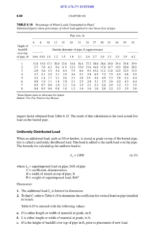
TABLE 6.18 Percentage of Wheel Loads Transmitted to Pipes *
Tabulated figures show percentage of wheel load applied to one linear foot of pipe.
Pipe size, in
6 8 10 12 15 18 21 24 27 30 33 36 39 42
Depth of
backfill Outside diameter of pipe, ft (approximate)
over top
of pipe, ft 0.64 0.81 1.0 1.2 1.5 1.8 2.1 2.4 2.7 3.0 3.3 3.5 3.9 4.2
1 12.8 15.0 17.3 20.0 22.6 24.8 26.4 27.2 28.0 28.6 29.0 29.4 29.8 29.9
2 5.7 7.0 8.3 9.6 11.5 13.2 15.0 15.6 16.8 17.8 18.7 19.5 20.0 20.5
3 2.9 3.6 4.3 5.2 6.4 7.5 8.6 9.3 10.2 11.2 11.8 12.5 12.9 13.5
4 1.7 2.1 2.5 3.1 3.9 4.6 5.3 5.8 6.5 7.2 7.9 8.5 8.8 9.2
5 1.2 1.4 1.7 2.1 2.6 3.1 3.6 3.9 4.4 4.9 5.3 5.8 6.1 6.4
6 0.8 1.0 1.1 1.4 1.8 2.1 2.5 2.8 3.1 3.5 3.8 4.2 4.3 4.4
7 0.5 0.7 0.8 1.0 1.3 1.6 1.9 2.1 2.3 2.6 2.9 3.2 3.3 3.5
8 0.4 0.5 0.6 0.8 1.0 1.2 1.4 1.6 1.8 2.0 2.2 2.3 2.5 2.6
*
These figures make no allowance for impact.
Source: Clay Pipe Engineering Manual.
impact factor obtained from Table 6.15. The result of this calculation is the total actual live
load on the buried pipe.
Uniformly Distributed Load
When an additional load, such as fill or lumber, is stored at grade on top of the buried pipe,
this is called a uniformly distributed load. This load is added to the earth load over the pipe.
The formula for calculating the uniform load is:
L = CBW (6.15)
s
where L = superimposed load on pipe, lb/ft of pipe
s
C = coefficient, dimensionless
B = width of trench at top of pipe, ft
W = weight of superimposed load, lb/ft 2
Discussion:
1. The additional load L is limited in dimension.
s
2. To find C, refer to Table 6.19 to determine the coefficient for vertical load on pipe installed
in trench.
Table 6.19 is entered with the following values:
a. D is either length or width of material at grade, in ft.
b. L is either length or width of material at grade, in ft.
c. H is the height of backfill over top of pipe in ft, prior to placement of new load.
Downloaded from Digital Engineering Library @ McGraw-Hill (www.accessengineeringlibrary.com)
Copyright © 2009 The McGraw-Hill Companies. All rights reserved.
Any use is subject to the Terms of Use as given at the website.