
Page 288 - Failure Analysis Case Studies II
P. 288
273
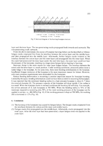
I--inner layer 2-cotton 3--mnddlc layer 4-stccl wrc laycr
5-middle layer 6--conon 7-outer layer
Fig. 9. Sectional diagram of the bursting hosepipe structure.
layer and the inner layer. The two penetrating cracks propagated both inwards and outwards. The
non-penetrating crack outwards.
From the above-mentioned, the course of hosepipe bursting failure can be described as follows:
fatigue cracks originated first from the interface between the cotton layer and the middle layer,
and then propagated into the middle layer. Afterwards, further fatigue cracks initiated at the
interface between the cotton layer and the inner layer and propagated into the inner layer. When
the crack had penetrated the inner layer under the steel wire layer, the outer layer could not bear
the pressure of the kerosene, resulting in a large stress fatigue failure leading to bursting.
Improper design is the main reason for inner layer fatigue failure. The interface between the
cotton and the inner layer is a weak position. Under working conditions, pressured pulses cause a
radial bulge in the hosepipe. At the same time, there were bending deformations in the hosepipe.
Insufficient fatigue resistance of the hosepipe is the most important reason for failure. However,
only static pressure requirements were demanded for the hosepipes.
Serious bending deformation in mounting is another important reason for hosepipe bursting.
Limited by the space, bending deformation could not have been avoided in mounting the hosepipes.
It was reported that the minimum bending radius in a high pressure hosepipe is about 6-7 times
the external diameter [I]. The pressure capacity of the hosepipe will drop rapidly if the radius is
too small. When the hosepipe works in normal conditions the working life will drop. For example,
the service pressure of A style hosepipes is 700 MPa. When the bending radius is 70% of the
minimum required in mounting only 58% of the rated working pressure of the hosepipe can be
applied in service, i.e., 406 MPa (Fig. IO). If the working pressure is kept at 700 MPa, the working
life is shortened to 12% (Fig. 10).
6. Conclusions
(1) The bursting of the hosepipes was caused by fatigue failure. The fatigue cracks originated from
the interfaces between the cotton and the inner and middle layers.
(2) Fatigue cracks first propagated into the middle layer. Afterwards, cracks propagated into the
inner layer. After the inner layer had been penetrated, a layer fatigue stress was applied to the
outer layer.