
Page 293 - Failure Analysis Case Studies II
P. 293
278
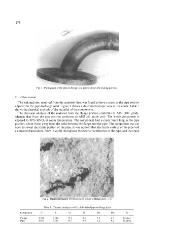
Fig. 1. Photograph of the pipe-to-flange joint (arrow shows the leaking portion).
2.1. Observations
The leaking joint, removed from the assembly line, was found to have a crack in the pipe portion
adjacent to the pipe-to-flange weld. Figure 2 shows a stereomicroscopic view of the crack. Table 1
shows the chemical analysis of the material of the components.
The chemical analysis of the material from the flange portion conforms to AISI 304L grade,
whereas that from the pipe portion conforms to AISI 304 grade only. The whole component is
exposed to 90% HNOS at room temperature. The component had a crack 5mm long in the pipe
portion, about 4mm away from the weld between the flange and the pipe. The component was cut
open to reveal the inside portion of the pipe. It was noticed that the inside surface of the pipe had
a corroded band about 7 mm in width throughout the inner circumference of the pipe, and the crack
l
I
Fig 2 Stereomicrograph of the crack on a pipe-to-flange joint x 16
Table 1 Chemical analysis (wtX) of the failed pipe-to-flange joint
Component C S Cr Ni Mn Mo Fe
~~ ~~~
Flange 0 034 0 010 19 3 98 13 03 Balance
Pipe 0 093 0011 19 7 94 12 02 Balance