
Page 298 - Failure Analysis Case Studies II
P. 298
283
f
e-
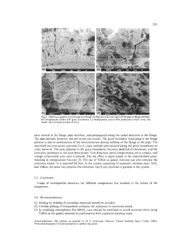
Fig. 8. SI:M fractographs ol'fai1r.d right port rlangc.. (a) Radial cmck, \tarring I'rorn thc. pip-to-llangc intcri,ice.
(h) Intergranular cracks with grain dissolution. (c) 1ntergranul;ir cracks nith prefcrenti.ll attxk :ildng 'Ilp
bands. (d) Corrosion product (Fe,O,).
have started at the flange-pipe interface, and propagated along the radial direction in the flange.
The pipe portion, however, did not reveal any cracks. The grain boundary thickening in the flange
portion is due to sensitization of the microstructure during welding of the flange to the pipe. The
sensitized microstructure contains Cr&-type carbides precipitated along the grain boundaries in
a fine network. The area adjacent to the grain boundaries becomes depleted of chromium, and the
corrosion resistance in this area deteriorates. Two dissimilar metal compositions are in contact, and
a large unfavorable area ratio is present. The net effect is rapid attack in the impoverished areas,
resulting in intergranular fracture [3]. The use of Teflon as gasket material can also enhance the
corrosion attack. It is reported [4] that, in the system consisting of austenitic stainless steel, N204
and Teflon, the latter can enhance the corrosion rate if any moisture is present in the system.
3.3. Conclusion
Usage of incompatible materials for different components has resulted in the failure of the
component.
3.4. Recommendations
(1) Joining by welding of dissimilar materials should be avoided.
(2) Chrome plating of components enhances the resistance to corrosion attack.
(3) In oxidizing atmospheres like HNO,, care should be exercised to avoid moisture while using
Teflon as the gasket material in combination with austenitic stainless steels.
Acknowledgement-The authors are grateful to Dr S. Srinivasan, Director, Vikram Sarabhai Space Centre, ISRO,
Thiruvananthapuram for kind permission to publish this paper.