
Page 294 - Failure Analysis Case Studies II
P. 294
279
(d)
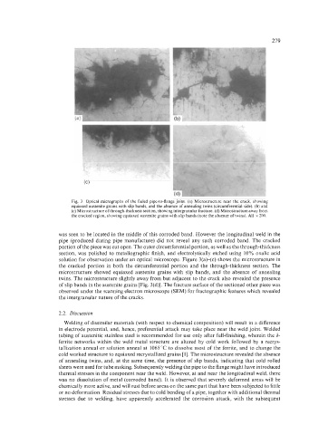
Fig. 3. Optical micrographs of the failed pipe-to-flange joint. (a) Microstructure near the crack, showing
equiaxed austenite grains with slip bands, and the absence of annealing twins (circumferential side). (b) and
(c) Microstructure of through-thickness section, showing intergranular fracture. (d) Microstructure away from
the cracked region, showing equiaxed austenite grains with slip bands (note the absence of twins). All x 200.
was seen to be located in the middle of this corroded band. However the longitudinal weld in the
pipe (produced during pipe manufacture) did not reveal any such corroded band. The cracked
portion of the piece was cut open. The outer circumferential portion, as well as the through-thickness
section, was polished to metallographic finish, and electrolytically etched using 10% oxalic acid
solution for observation under an optical microscope. Figure 3(ak(c) shows the microstructure in
the cracked portion in both the circumferential portion and the through-thickness section. The
microstructure showed equiaxed austenite grains with slip bands, and the absence of annealing
twins. The microstructure slightly away from but adjacent to the crack also revealed the presence
of slip bands in the austenite grains [Fig. 3(d)]. The fracture surface of the sectioned other piece was
observed under the scanning electron microscope (SEM) for fractographic features which revealed
the intergranular nature of the cracks.
2.2. Discussion
Welding of dissimilar materials (with respect to chemical composition) will result in a difference
in electrode potential, and, hence, preferential attack may take place near the weld joint. Welded
tubing of austenitic stainless steel is recommended for use only after full-finishing, wherein the 6-
ferrite networks within the weld metal structure are altered by cold work followed by a recrys-
tallization anneal or solution anneal at 1065 "C to dissolve most of the ferrite, and to change the
cold worked structure to equiaxed recrystallized grains [ 13. The microstructure revealed the absence
of annealing twins, and, at the same time, the presence of slip bands, indicating that cold rolled
sheets were used for tube making. Subsequently welding the pipe to the flange might have introduced
thermal stresses in the component near the weld. However, at and near the longitudinal weld, there
was no dissolution of metal (corroded band). It is observed that severely deformed areas will be
chemically more active, and will rust before areas on the same part that have been subjected to little
or no deformation. Residual stresses due to cold bending of a pipe, together with additional thermal
stresses due to welding, have apparently accelerated the corrosion attack, with the subsequent