
Page 295 - Failure Analysis Case Studies II
P. 295
280
formation of a corroded band and crack initiation within the band during 7 years of service.
Intergranular cracks, typical of stress corrosion attack, as noticed on the fracture surface, are
the evidence for such stress-induced preferential attack along the grain boundaries. This type of
intergranular fracture is typical of the HN03 stainless steel system [2]. The pipe-to-flange weld has
a longer thermal mass than the pipe weld, so presumably required a comparatively large input.
Because of the high carbon content of the pipe, sensitization may have occurred in the pipe-to-
flange weld as a result of the weld thermal cycle.
2.3. Conclusions
Cold working and welding processes used for component fabrication introduced stresses. Welding
of dissimilar metal compositions introduced electrode potential differences. This combination
created conditions conducive to preferential corrosion attack. Sensitization may also have been a
factor owing to the high carbon content of the pipe, and the high heat input which may have been
required to make the pipe-to-flange weld.
2.4. Recommendations
(1) Components should be given an annealing treatment after fabrication processes like bending,
welding etc.
(2) Joining by welding of dissimilar materials should be avoided.
(3) Possible sensitization can be avoided by using the L grade of stainless steel.
3. CASE STUDY 11: FAILURE OF SIGHT PORT FLANGE
The second case study refers to the failure of the sight port flange, which was located between
flanges in the NO absorption column. Austenitic stainless steel AIS1 304L pipe of 80mm OD and
75 mm ID was welded to a flange which was also said to be made of similar steel. A Teflon gasket
was used between the flanges to provide a leak-proof system.
3.1. Observations
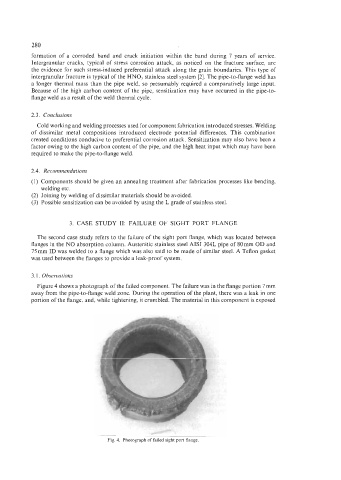
Figure 4 shows a photograph of the failed component. The failure was in the flange portion 7 mm
away from the pipe-to-flange weld zone. During the operation of the plant, there was a leak in one
portion of the flange, and, while tightening, it crumbled. The material in this component is exposed
Fig. 4. Photograph of failed sight port flange.