
Page 297 - Failure Analysis Case Studies II
P. 297
282
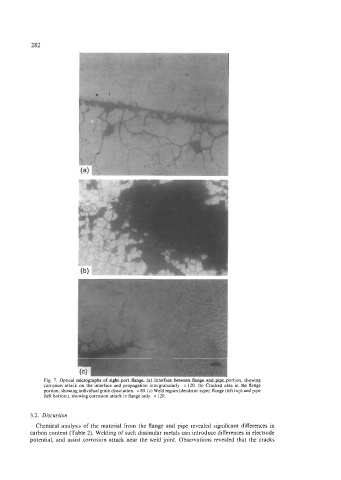
Fig. 7. Optical micrographs of sight port flange. (a) Interface between flange and pipe portion, showing
corrosion attack on the interface and propagation intergranularly. x 120. (b) Cracked area in the flange
portion, showing individual grain dissolution. x 80. (c) Weld region (dendritic type), flange (left top) and pipe
(left bottom), showing corrosion attack in flange only. x 120.
3.2. Discussion
Chemical analysis of the material from the flange and pipe revealed significant differences in
carbon content (Table 2). Welding of such dissimilar metals can introduce differences in electrode
potential, and assist corrosion attack near the weld joint. Observations revealed that the cracks