
Page 300 - Failure Analysis Case Studies II
P. 300
285
CORROSION OF CENTRAL HEATING SYSTEMS
D. R. H. JONES
Department of Engineering, University of Cambridge, Trumpington Street, Cambridge CB2 IPZ, U.K.
(Received 20 March 1YY7)
Abstract-This paper begins by summarizing the main mechanisms by which components in central heating
systems can corrode, and indicating the factors which can increase or decrease the rates of corrosion. The
basic principles are then applied to the analysis of three case studies of corrosion failure in heating systems:
rusting through of mild steel radiators after only 2 years in service; premature pitting corrosion of aluminium
heat-exchanger tubes; and external corrosion of mild steel water pipes. Q 1997 Elsevier Science Ltd
Keywords: Bacterial corrosion, corrosion, corrosion protection, pitting corrosion, heat-exchanger failures
1. BACKGROUND
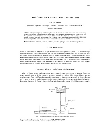
Figure 1 is a schematic diagram of a typical closed recirculating heating system. The heat-exchange
medium (water) is circulated between the heat source (boiler) and the heat sink (radiators). The
maximum water temperature at the exit from the boiler is typically 80 "C. A typical radiator is made
from two separate sheets of mild steel 1-2 mm thick, which are press-formed to produce the shapes
of the waterways, and joined by electrical-resistance welding (Fig. 2). The water pipes are generally
made from thin-walled copper tube. The heating modules in the boiler are made from steel, copper
or aluminium alloy. Fittings such as valves are usually made from brass.
2. OXYGEN REDUCTION-BASIC MECHANISMS
Mild steel has a strong tendency to rust when exposed to water and oxygen. Because the mains
water which is used to fill the system is saturated with air, one might think that mild steel was an
unwise choice ofmaterial for radiators and heat exchangers. As shown in Appendix A, the conditions
under which a metal corrodes in water can be summarized using the electrochemical equilbrium (or
Pourbaix) diagram [I]. Figure 3 shows the Pourbaix diagram for iron at 25 "C. Mains water usually
~ 171 """ rmq=
Radiator
~
Return
Fig. 1. Schematic diagram of a closed recirculating heating system.
Reprinted from Engineering Failure Analysis 4 (3), 179-1 94 (I 997)