
Page 439 - Failure Analysis Case Studies II
P. 439
422
Cr depletion of up to 1.40% near the surface region; this shows that the balls were running hot for
quite some time.
3. FRACTOGRAPHY OF THE CAGE FRACTURE STRUCTURE
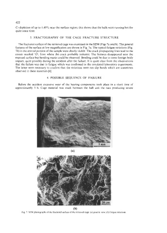
The fractured surface of the retrieved cage was examined in the SEM (Figs 7a and b). The general
features of the surface at low magnification are shown in Fig. 7a. The typical fatigue striations (Fig.
7b) in the central portion of the sample were clearly visible. The crack propagating lines lead to the
corner marked ‘0’; from where the crack probably initiated. The features disappeared near the
exposed surface but bending marks could be observed. Bending could be due to some foreign body
impact, quite possibly during the accident after the failure. It is quite clear from the observations
that the failure was due to fatigue which was confirmed in the simulated laboratory experiments.
The latter were necessary to confirm that the striations were not slip bands which are sometimes
observed in these materials [4].
4. POSSIBLE SEQUENCE OF FAILURE
Before the accident excessive wear of the bearing components took place in a short time of
approximately 5 h. Cage material was stuck between the ball and the race producing severe
(b)
Fig. 7. SEM photographs of the fractured surface of the retrieved cage: (a) general view; (b) fatigue striations.