
Page 70 - Failure Analysis Case Studies II
P. 70
55
fl work wire
B
chain
seabed
anchor B
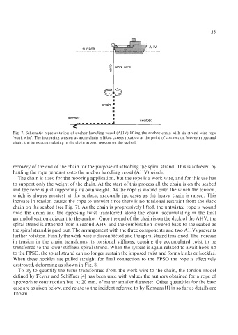
Fig. 7. Schematic representation of anchor handling vessel (AHV) lifting the anchor chain with six strand wire rope
‘work wire’. The increasing tension as more chain is lifted causes rotation at the point of connection between rope and
chain, the turns accumulating in the chain at zero tension on the seabed.
recovery of the end of the chain for the purpose of attaching the spiral strand. This is achieved by
hauling the rope pendant onto the anchor handling vessel (AHV) winch.
The chain is sized for the mooring application, but the rope is a work wire, and for this use has
to support only the weight of the chain. At the start of this process all the chain is on the seabed
and the rope is just supporting its own weight. As the rope is wound onto the winch the tension,
which is always greatest at the surface, gradually increases as the heavy chain is raised. This
increase in tension causes the rope to untwist since there is no torsional restraint from the slack
chain on the seabed (see Fig. 7). As the chain is progressively lifted, the untwisted rope is wound
onto the drum and the opposing twist transferred along the chain, accumulating in the final
grounded section adjacent to the anchor. Once the end of the chain is on the deck of the AHV, the
spiral strand is attached from a second AHV and the combination lowered back to the seabed as
the spiral strand is paid out. The arrangement with the three components and two AHVs prevents
further rotation. Finally the work wire is disconnected and the spiral strand tensioned. The increase
in tension in the chain transforms its torsional stiffness, causing the accumulated twist to be
transferred to the lower stiffness spiral strand. When the system is again relaxed to await hook up
to the FPSO, the spiral strand can no longer sustain the imposed twist and forms kinks or hockles.
When these hockles are pulled straight for final connection to the FPSO the rope is effectively
destroyed, deforming as shown in Fig. 8.
To try to quantify the turns transformed from the work wire to the chain, the torsion model
defined by Feyrer and Schiffner [4] has been used with values the authors obtained for a rope of
appropriate construction but, at 20 mm, of rather smaller diameter. Other quantities for the base
case are as given below, and relate to the incident referred to by Komura [ 11 in so far as details are
known.