
Page 91 - Failure Analysis Case Studies II
P. 91
76
tensile creep rupture design and failure data for this case. Although creep-rupture does not occur
in compression, it is expected that strain rates will be similar for tension and compression.
Strain limits associated with allowable stresses are in the region of 1 %. Significantly more strain
will accumulate if stresses approach the rupture limit, so using design failure stresses in compression
to assure strain limits is justifiable.
Stress analyses were performed on two details of the drier:
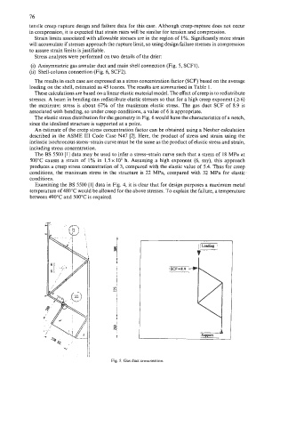
(i) Axisymmetric gas annular duct and main shell connection (Fig. 5, SCF1).
(ii) Shell-column connection (Fig. 6, SCF2).
The results in each case are expressed as a stress concentration factor (SCF) based on the average
loading on the shell, estimated as 45 tonnes. The results are summarised in Table 1.
These calculations are based on a hear elastic material model. The effect of creep is to redistribute
stresses. A beam in bending can redistribute elastic stresses so that for a high creep exponent (86)
the maximum stress is about 67% of the maximum elastic stress. The gas duct SCF of 8.9 is
associated with bending, so under creep conditions, a value of 6 is appropriate.
The elastic stress distribution for the geometry in Fig. 6 would have the characteristics of a notch,
since the idealised structure is supported at a point.
An estimate of the creep stress concentration factor can be obtained using a Neuber calculation
described in the ASME I11 Code Case N47 [2]. Here, the product of stress and strain using the
inelastic isochronous stress-strain curve must be the same as the product of elastic stress and strain,
including stress concentration.
The BS 5500 [I] data may be used to infer a stress-strain curve such that a stress of 18 MPa at
500°C causes a strain of 1% in 1.5 x IO5 h. Assuming a high exponent (6, say), this approach
produces a creep stress concentration of 3, compared with the elastic value of 5.4. Thus for creep
conditions, the maximum stress in the structure is 22 MPa, compared with 32 MPa for elastic
conditions.
Examining the BS 5500 [I] data in Fig. 4, it is clear that for design purposes a maximum metal
temperature of 480°C would be allowed for the above stresses. To explain the failure, a temperature
between 490°C and 500°C is required.
t i
%I
I
I
Fig. 5. Gas duct cross-section.