
Page 275 - Fair, Geyer, and Okun's Water and wastewater engineering : water supply and wastewater removal
P. 275
JWCL344_ch07_230-264.qxd 8/2/10 8:44 PM Page 235
7.5 Network Analysis 235
A H L3 C
H L1 H L2
B
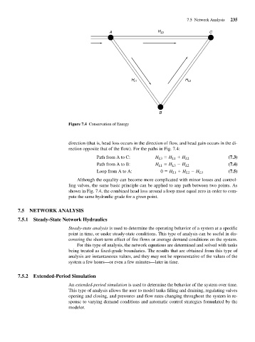
Figure 7.4 Conservation of Energy
direction (that is, head loss occurs in the direction of flow, and head gain occurs in the di-
rection opposite that of the flow). For the paths in Fig. 7.4:
Path from A to C: H L3 H L1 H L2 (7.3)
Path from A to B: H L1 H L3 H L2 (7.4)
Loop from A to A: 0 H L1 H L2 H L3 (7.5)
Although the equality can become more complicated with minor losses and control-
ling valves, the same basic principle can be applied to any path between two points. As
shown in Fig. 7.4, the combined head loss around a loop must equal zero in order to com-
pute the same hydraulic grade for a given point.
7.5 NETWORK ANALYSIS
7.5.1 Steady-State Network Hydraulics
Steady-state analysis is used to determine the operating behavior of a system at a specific
point in time, or under steady-state conditions. This type of analysis can be useful in dis-
covering the short-term effect of fire flows or average demand conditions on the system.
For this type of analysis, the network equations are determined and solved with tanks
being treated as fixed-grade boundaries. The results that are obtained from this type of
analysis are instantaneous values, and they may not be representative of the values of the
system a few hours—or even a few minutes—later in time.
7.5.2 Extended-Period Simulation
An extended-period simulation is used to determine the behavior of the system over time.
This type of analysis allows the user to model tanks filling and draining, regulating valves
opening and closing, and pressures and flow rates changing throughout the system in re-
sponse to varying demand conditions and automatic control strategies formulated by the
modeler.