
Page 323 - Fair, Geyer, and Okun's Water and wastewater engineering : water supply and wastewater removal
P. 323
JWCL344_ch08_265-296.qxd 8/2/10 9:53 PM Page 283
8.6 Types of Distributing Reservoirs 283
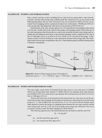
EXAMPLE 8.8 PUMPING AND STORAGE SYSTEM
Draw a sketch, showing a system (including the raw water reservoir, pump station, water transmis-
sion lines, elevated water storage tank, hydraulic grade line, elevation in ft or m, etc.) based on the
following information: The raw water reservoir of a city is at an elevation of 500 ft (152.4 m). An au-
3
tomatic booster pumping station is proposed, having for its control point a 550,000-gal (2,082 m )
water storage tank. The design tank water level is at an elevation of 490 ft (149.4 m).
Measurement of the water storage tank level is to be transmitted to the pumping station and is
to be the only variable used for the control of the pumps in the pumping station. The head losses of
the water transmission line between the raw water reservoir and the elevated water storage tank (in-
cluding the miscellaneous head losses in the proposed pumping station) computed for the rate of
flow of 1,600 gpm (101 L/s), are 40 ft or (12.2 m), which is to be overcome by the pumps. A chlo-
rination system is used for treating the water entering the elevated water storage tank. The chlori-
nated water from the tank is transmitted to the city’s water filtration plant for further treatment prior
to domestic consumption.
Solution:
El. 500 ft
El. 490'
Hydraulic
grade line
40 ft
at 1600 gpm
Figure 8.11 Sketch of Water Supply System for Example 8.8
3
Conversion factors: 1 1 ft 0.3048 m; 1 gpm 3.785 L/min 0.0000631 m /s 0.0631 L/s.
EXAMPLE 8.9 PUMPS AND WATER STORAGE TANKS
The water supply system shown in Example 8.8 provides water to a city at the rates of 2.0 MGD
(88 L/s) for average daily water demand, 3.4 MGD (150 L/s) for maximum daily water demand,
and 4.8 MGD (210 L/s) for peak hourly water demand. The total head losses are 40 ft (12.2 m) at a
flow of 1,600 gpm (101 L/s).
What are the head losses of the transmission line between the raw water reservoir and the ele-
vated water storage tank (including all miscellaneous head losses), which must be overcome by the
pumps at 2, 3.4, and 4.8 MGD (88, 150, and 210 L/s; or 7.6, 12.9, and 18.2 MLD)? Explain which
water demand is used for the design of a pumping station between the raw water reservoir and the
water storage tank, and why. Is the size of the existing water storage tank sufficient for the city in
accordance with the current Ten-States Standards for Water Works?
The following equation shows the relationship between the head loss and the water flow:
H 2 H 1 (Q 2 >Q 1 ) 2
where
3
Q 1 the first water flow, gpm (m /s)
3
Q 2 the second water flow, gpm (m /s)