
Page 326 - Fair, Geyer, and Okun's Water and wastewater engineering : water supply and wastewater removal
P. 326
JWCL344_ch08_265-296.qxd 8/2/10 9:53 PM Page 286
286 Chapter 8 Pumping, Storage, and Dual Water Systems
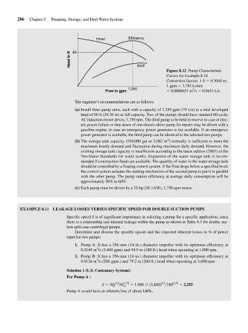
Efficiency
Head
Head in ft 80
BHP
Figure 8.12 Pump Characteristic
Curves for Example 8.10
Conversion factors: 1 ft 0.3048 m;
1 gpm 3.785 L/min
3
Flow in gpm 1,250 0.0000631 m /s 0.0631 L/s
The engineer’s recommendations are as follows:
(a) Install three pump units, each with a capacity of 1,250 gpm (79 L/s) at a total developed
head of 80 ft (24.38 m) at full capacity. Two of the pumps should have standard 60-cycle,
AC induction-motor drives, 1,750 rpm. The third pump to be held in reserve in case of elec-
tric power failure or shut down of one electric-drive pump for repairs may be driven with a
gasoline engine, in case an emergency power generator is not available. If an emergency
power generator is available, the third pump can be identical to the selected two pumps.
3
(b) The storage tank capacity (550,000 gal or 2,082 m ) normally is sufficient to meet the
maximum hourly demand and fluctuation during maximum daily demand. However, the
existing storage tank capacity is insufficient according to the latest edition (2007) of the
Ten-States Standards for water works. Expansion of the water storage tank is recom-
mended if construction funds are available. The quantity of water in the water storage tank
should be controlled by a floating control system. If the float drops below a specified level,
the control system actuates the starting mechanism of the second pump to put it in parallel
with the other pump. The pump station efficiency at average daily consumption will be
approximately 50% to 60%.
(c) Each pump must be driven by a 35-hp (26.1-kW), 1,750-rpm motor.
EXAMPLE 8.11 LEAKAGE LOSSES VERSUS SPECIFIC SPEED FOR DOUBLE SUCTION PUMPS
Specific speed S is of significant importance in selecting a pump for a specific application, since
there is a relationship and internal leakage within the pump as shown in Table 8.3 for double suc-
tion split case centrifugal pumps.
Determine and discuss the specific speeds and the expected inherent losses in % of power
input for two pumps:
1. Pump A: It has a 356-mm (14-in.) diameter impeller with its optimum efficiency at
3
0.2145 m /s (3,400 gpm) and 54.9 m (180-ft.) head when operating at 1,900 rpm.
2. Pump B: It has a 356-mm (14-in.) diameter impeller with its optimum efficiency at
3
0.0126 m /s (200-gpm.) and 79.2 m (260-ft.) head when operating at 3,600 rpm
Solution 1 (U.S. Customary System):
For Pump A :
0.5 0.75 0.5 0.75
S NQ /H sv 1,900 (3,400) >180 2,255
Pump A would have an inherent loss of about 1.6%.