
Page 467 - Fair, Geyer, and Okun's Water and wastewater engineering : water supply and wastewater removal
P. 467
JWCL344_ch12_398-456.qxd 8/4/10 9:37 PM Page 425
12.5 Urban Runoff Control Practices 425
Concrete level
Parking lot spreader
Grass channel
Plunge
pool
Bypass
(to detention facility)
Infiltration
trench
Overflow
Plan view
Runoff filters through grass
Observation well
Overflow berm with screw top LID buffer strip; grass channel;
or sedimentation vault
PEA gravel filter layer
Protective layer of filter fabric
Trench filled with 1.5 2.5 in.
diameter clean stone
Sand filter
(or fabric equivalent)
Runoff exfiltrates through
undisturbed subsoils with a
minimum rate of 0.5 in./h
Section
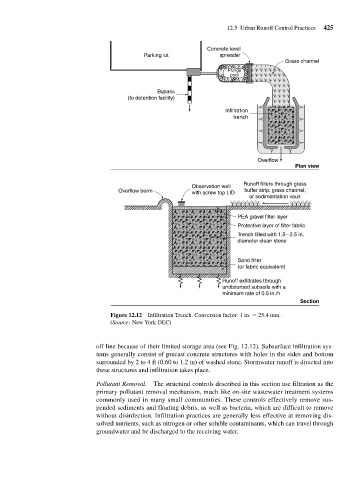
Figure 12.12 Infiltration Trench. Conversion factor: 1 in. 25.4 mm.
(Source: New York DEC)
off line because of their limited storage area (see Fig. 12.12). Subsurface infiltration sys-
tems generally consist of precast concrete structures with holes in the sides and bottom
surrounded by 2 to 4 ft (0.60 to 1.2 m) of washed stone. Stormwater runoff is directed into
these structures and infiltration takes place.
Pollutant Removal. The structural controls described in this section use filtration as the
primary pollutant removal mechanism, much like on-site wastewater treatment systems
commonly used in many small communities. These controls effectively remove sus-
pended sediments and floating debris, as well as bacteria, which are difficult to remove
without disinfection. Infiltration practices are generally less effective at removing dis-
solved nutrients, such as nitrogen or other soluble contaminants, which can travel through
groundwater and be discharged to the receiving water.