Page 472 - Fair, Geyer, and Okun's Water and wastewater engineering : water supply and wastewater removal
P. 472

JWCL344_ch12_398-456.qxd  8/4/10  9:37 PM  Page 430


                    430  Chapter 12  Urban Runoff and Combined Sewer Overflow Management

                                                                                         Street tree, typ., offset
                                                    Rock or concrete check                to street side, 2.5 ft
                                                     dams@ 12´ intervals                   from back of curb


                                                                                          12˝ min. area
                                               Min. 12˝ flat area                        w/max 4:1 slope
                                               next to sidewalk
                                                                                                  Standard curb
                                                                                                w/curb cut spillways
                                           Top of sidewalk
                                           elev.    street
                                             gutter ele                                             Street surface


                                                                                                     6˝ min. from
                                                                                                     curb cut to
                                                                      12˝ overlap                    bottom of swale
                                                                                                Line street edge w/
                                          3:1 max. side slopes
                                                                                                impermeable
                                                                                                membrane or clay
                                                                                                12˝ sandy loam topsoil
                                                                Rock trench width 3 ft. minimum
                                                             Swale width 7 ft. minimum in public ROW

                                           Use woven monofilament                      If needed per design procedure:
                                                                                       1
                                                                                          3
                                            filter fabric, Geotex WM-                 1   2 ˝    4 ˝ washed drain rock, except
                                          111F or fabric with equivalent  Not to scale  in tree wells, minimum void ratio
                                           strength and permeability,               (V%)   30%, trench width (3 ft minimum)
                                          to separate topsoil from drain               and depth to be determined per
                                           rock, no fabric in tree wells.          surface infiltration facility design procedure
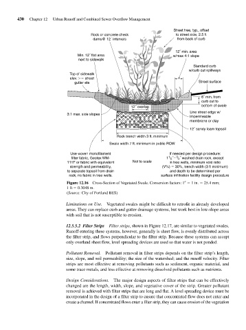
                                          Figure 12.16 Cross-Section of Vegetated Swale. Conversion factors: 1    1 in.   25.4 mm;
                                          1 ft   0.3048 m.
                                          (Source: City of Portland BES)
                                         Limitations on Use.  Vegetated swales might be difficult to retrofit in already developed
                                         areas. They can replace curb and gutter drainage systems, but work best in low-slope areas
                                         with soil that is not susceptible to erosion.
                                         12.5.5.2 Filter Strips Filter strips, shown in Figure 12.17, are similar to vegetated swales.
                                         Runoff entering these systems, however, generally is sheet flow, is evenly distributed across
                                         the filter strip, and flows perpendicular to the filter strip. Because these systems can accept
                                         only overland sheet flow, level spreading devices are used so that water is not ponded.

                                         Pollutant Removal.  Pollutant removal in filter strips depends on the filter strip’s length,
                                         size, slope, and soil permeability; the size of the watershed; and the runoff velocity. Filter
                                         strips are most effective at removing pollutants such as sediment, organic material, and
                                         some trace metals, and less effective at removing dissolved pollutants such as nutrients.


                                         Design Considerations.  The major design aspects of filter strips that can be effectively
                                         changed are the length, width, slope, and vegetative cover of the strip. Greater pollutant
                                         removal is achieved with filter strips that are long and flat. A level spreading device must be
                                         incorporated in the design of a filter strip to ensure that concentrated flow does not enter and
                                         create a channel. If concentrated flows enter a filter strip, they can cause erosion of the vegetation
   467   468   469   470   471   472   473   474   475   476   477