Page 475 - Fair, Geyer, and Okun's Water and wastewater engineering : water supply and wastewater removal
P. 475

JWCL344_ch12_398-456.qxd  8/4/10  9:37 PM  Page 433


                                                                                 12.5 Urban Runoff Control Practices  433

                                                                        Plan view
                                                                            Flow                 A


                                                           Grated cover
                                                                                                  Sediment
                                                                                                    trap

                                                                                              Sand
                                                                                                            Drain


                                                                                                        Outfall pipe

                                                                                                     A

                                                                        Section A-A
                                                                   Grated cover  Solid cover
                                                                 6 in.                6 in.
                                                       Flow                                     Paving
                                                                      10 in.
                                                                               12 in.
                                            1   2 -in. reinforcement bars       Sand
                                            6-in. on center each way                       Outfall pipe
                                                3,000 psi concrete
                                                           6 in.
                                                                                              Provide nipple, fittings,
                                                                                              etc. as required
                                                                 Grate (fabric wrapped
                                                              over entire grate opening)

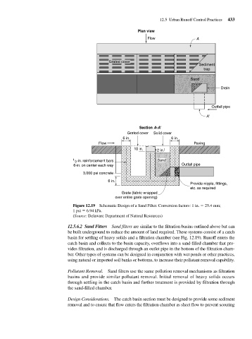
                                            Figure 12.19 Schematic Design of a Sand Filter. Conversion factors: 1 in.   25.4 mm;
                                            1 psi   6.94 kPa.
                                            (Source: Delaware Department of Natural Resources)

                                         12.5.6.2 Sand Fitters Sand filters are similar to the filtration basins outlined above but can
                                         be built underground to reduce the amount of land required. These systems consist of a catch
                                         basin for settling of heavy solids and a filtration chamber (see Fig. 12.19). Runoff enters the
                                         catch basin and collects to the basin capacity, overflows into a sand-filled chamber that pro-
                                         vides filtration, and is discharged through an outlet pipe in the bottom of the filtration cham-
                                         ber. Other types of systems can be designed in conjunction with wet ponds or other practices,
                                         using natural or imported soil banks or bottoms, to increase their pollutant removal capability.

                                         Pollutant Removal.  Sand filters use the same pollution removal mechanisms as filtration
                                         basins and provide similar pollutant removal. Initial removal of heavy solids occurs
                                         through settling in the catch basin and further treatment is provided by filtration through
                                         the sand-filled chamber.
                                         Design Considerations. The catch basin section must be designed to provide some sediment
                                         removal and to ensure that flow enters the filtration chamber as sheet flow to prevent scouring
   470   471   472   473   474   475   476   477   478   479   480