
Page 501 - Fair, Geyer, and Okun's Water and wastewater engineering : water supply and wastewater removal
P. 501
JWCL344_ch13_457-499.qxd 8/7/10 8:49 PM Page 459
13.2 Flow in Filled Sewers 459
2,000 0.3
0.005
1,000 1,500 0.6 0.2
800 0.006
0.007
1,000 0.7
600 0.008
500 800 Reference axis Velocity head in ft 0.009 0.8 0.1
0.01
400 600 0.08
500 0.9 0.06
300 0.05
400 1.0 0.04
20
200 300 0.03
0.02
15 0.02
200
100 0.03
80 10 0.04 1.5 0.01
100 9 0.008
60 96 8 Diameter of pipe D in ft 0.10 0.05
50 80 0.006
84 7 0.08 0.005
40 60 72 6 0.06 0.06 2 0.004
50 0.05 0.07 0.003
30 40 60 5 0.04 0.08 0.002
Discharge, Q in MGD 20 30 Discharge, Q in ft 3 /s Diameter of pipe, D in inches 42 3 Q, D and V n and S Manning coefficient, n 0.02 3 Velocity, V in ft/s Slope, S 0.001
0.09
54
0.03
0.1
4
48
0.015
36
20
33
0.010
10
27
0.0006
8 30 0.008 0.2 0.0008
0.006
24
0.0005
10 21 4
6 0.0004
5 8 18 0.3 0.0003
4 6 15 5
0.4 0.0002
5
3
12 0.5
4
6
10
2 3 0.6 0.0001
0.7 0.00008
8 7
0.8
2 0.00006
0.9 0.00005
1.0 6 1.0 8 0.00004
0.8 9 0.00003
1.0
0.6 4 10 0.00002
0.5 0.8
2
0.4 0.6
0.5 0.00001
0.3
0.4 3 0.000008
15 0.000006
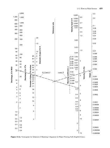
Figure 13.1a Nomogram for Solution of Manning’s Equation for Pipes Flowing Full (English Units).