Page 54 - Fair, Geyer, and Okun's Water and wastewater engineering : water supply and wastewater removal
P. 54

JWCL344_ch01_001-028.qxd  8/2/10  9:12 PM  Page 17


                                                                                           1.8 Transmission Works  17


                                                                            3
                                                                                                 2
                                                (c) Surface area A   V>H   (1,576 m )>(3.05 m – 0.61 m)   646 m (such as 10.7 m by
                                                   61 m).
                                                                                                      2
                                                                                        2
                                                (d) Surface rating SR   Q>A   (26,268 L/min)>(646 m )   40.7 L/min/m .
                                             4. Six rapid sand filters.
                                                                                    2
                                                (a) Assumed rating SR   Q>A   122.1 L/min/m ; number of filters N   6.
                                                                                                  2
                                                (b) Area A   Q>(N   SR)   (26,268 L/min)>(6   122.1)   35.86 m (such as 4.6 m by
                                                   7.9 m).

                    1.8 TRANSMISSION WORKS

                                         Supply conduits, or aqueducts, transport water from the source of supply to the commu-
                                         nity and so form the connecting link between collection works and distribution systems.
                                         Source location determines whether conduits are short or long, and whether transport is
                                         by gravity or pumping. Depending on topography and available materials, conduits are
                                         designed for open-channel or pressure flow. They may follow the hydraulic grade line
                                         as canals dug through the ground, flumes elevated above the ground, grade aqueducts
                                         laid in balanced cut and cover at the ground surface, and grade tunnels penetrating hills;
                                         or they may depart from the hydraulic grade line as pressure aqueducts laid in balanced
                                         cut and cover at the ground surface, pressure tunnels dipping beneath valleys or hills,
                                         and pipelines of fabricated materials following the ground surface, if necessary over
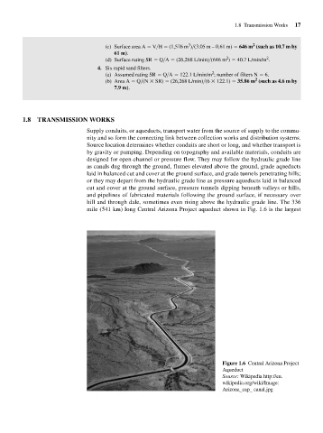
                                         hill and through dale, sometimes even rising above the hydraulic grade line. The 336
                                         mile (541 km) long Central Arizona Project aqueduct shown in Fig. 1.6 is the largest


                                                                                       Figure 1.6 Central Arizona Project
                                                                                       Aqueduct
                                                                                       Source: Wikipedia http://en.
                                                                                       wikipedia.org/wiki/Image:
                                                                                       Arizona_cap_ canal.jpg
   49   50   51   52   53   54   55   56   57   58   59