
Page 578 - Fair, Geyer, and Okun's Water and wastewater engineering : water supply and wastewater removal
P. 578
JWCL344_ch14_500-554.qxd 8/7/10 8:56 PM Page 534
534 Chapter 14 Design of Sewer Systems
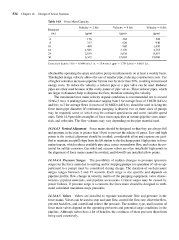
Table 14.9 Force Main Capacity
Velocity 2 ft/s Velocity 4 ft/s Velocity 6 ft/s
Diameter
(in.) (gpm) (gpm) (gpm)
6 176 362 528
8 313 626 940
10 490 980 1,470
18 1,585 3,170 4,755
24 2,819 5,638 8,457
36 6,342 12,684 19,086
Conversion factors: 1 ft/s 0.3048 m/s; 1 in. 25.4 mm; 1 gpm 3.785 L/min 0.0631 L/s.
obtained by operating the spare and active pump simultaneously on at least a weekly basis.
This higher design velocity allows the use of smaller pipe, reducing construction costs. Use
of higher velocities increases pipeline friction loss by more than 50%, resulting in increased
energy costs. To reduce the velocity, a reducer pipe or a pipe valve can be used. Reducer
pipes are often used because of the costly nature of pipe valves. These reducer pipes, which
are larger in diameter, help to disperse the flow, therefore reducing the velocity.
The maximum force main velocity at peak conditions is recommended not to exceed
10 ft/s (3 m/s). A peaking factor allowance ranging from 3 for average flows of 1 MGD (44 L/s)
and less, to 2 for average flows in excess of 10 MGD (440 L/s), should be used in sizing the
force main pipe diameter. If continuous pumping is desired, two or three sizes of pumps
may be required, some of which may be constant-speed units and some variable-speed
units. Table 14.9 provides examples of force main capacities at various pipeline sizes, mate-
rials, and velocities. The flow volumes may vary depending on the pipe material used.
14.14.4.3 Vertical Alignment Force mains should be designed so that they are always full
and pressure in the pipe is greater than 10 psi to prevent the release of gases. Low and high
points in the vertical alignment should be avoided; considerable effort and expense are justi-
fied to maintain an uphill slope from the lift station to the discharge point. High points in force
mains trap air, which reduces available pipe area, causes nonuniform flow, and creates the po-
tential for sulfide corrosion. Gas relief and vacuum valves are often installed if high points in
the alignment of force mains cannot be avoided, and blowoffs are installed at low points.
14.14.4.4 Pressure Surges The possibility of sudden changes in pressure (pressure
surges) in the force main due to starting and/or stopping pumps (or operation of valves ap-
purtenant to a pump) must be considered during design. The duration of such pressure
surges ranges between 2 and 15 seconds. Each surge is site specific and depends on
pipeline profile, flow, change in velocity, inertia of the pumping equipment, valve charac-
teristics, pipeline materials, and pipeline accessories. Critical surges may be caused by
power failures. If pressure surge is a concern, the force main should be designed to with-
stand calculated maximum surge pressures.
14.14.4.5 Valves Valves are installed to regulate wastewater flow and pressure in the
force mains. Valves can be used to stop and start flow, control the flow rate, divert the flow,
prevent backflow, and control and relieve the pressure. The number, type, and location of
force main valves depend on the operating pressures and potential surge conditions in the
pipeline. Although valves have a lot of benefits, the costliness of them prevents them from
being used extensively.