
Page 102 - Fiber Bragg Gratings
P. 102
3.1 Methods for fiber Bragg grating fabrication 81
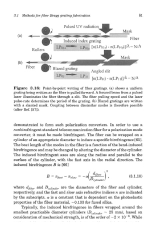
Figure 3.18: Point-by-point writing of fiber gratings, (a) shows a uniform
grating being written as the fiber is pulled forward. A focused beam from a pulsed
laser illuminates the fiber through a slit. The fiber pulling speed and the laser
pulse-rate determines the period of the grating, (b) Blazed gratings are written
with a slanted mask. Coupling between dissimilar modes is therefore possible
(after Ref. [57]).
demonstrated to form such polarization converters. In order to use a
noftbirefringent standard telecommunication fiber for a polarization mode
converter, it must be made birefringent. The fiber can be wrapped on a
cylinder of an appropriate diameter to induce a specific birefringence [65].
The beat length of the modes in the fiber is a function of the bend-induced
birefringence and may be changed by altering the diameter of the cylinder.
The induced birefringent axes are along the radius and parallel to the
surface of the cylinder, with the fast axis in the radial direction. The
induced birefringence B is [66]
where d fiber and D cylinder are the diameters of the fiber and cylinder,
respectively, and the fast and slow axis refractive indices n are indicated
by the subscripts, a is a constant that is dependent on the photoelastic
properties of the fiber material, —0.133 for fused silica.
Typically, the induced birefringence in fibers wrapped around the
smallest practicable diameter cylinders (D cyUnder ~ 25 mm), based on
6
consideration of mechanical strength, is of the order of —2 X 10~ . While