
Page 103 - Fiber Bragg Gratings
P. 103
82 Chapter 3 Fabrication of Bragg Gratings
this value is large compared to the intrinsic birefringence of standard
telecommunications fiber, it is well below that of birefringent optical fibers
2
(maximum birefringence B max ~ 0.4 X A/i , where An. is the core cladding
4
index difference [67]; for Arc = 0.04, B max ~ 6.4 X 10~ ). If a grating with
a period, Ag. = A/B is written in the fiber, then coupling between the two
polarizations will occur. However, the grating has to be written oriented
at 45° to the fast and slow axes. This may be done simply by arranging
the UV illumination in a direction of the axis of the cylinder but rotated
at an angle of 45° to the surface of the cylinder. As the fiber moves across
the slit, the laser is switched on so that half the period of the grating is
exposed to UV radiation before it is switched off for the second half. The
process is repeated until the required number of periods is written [591.
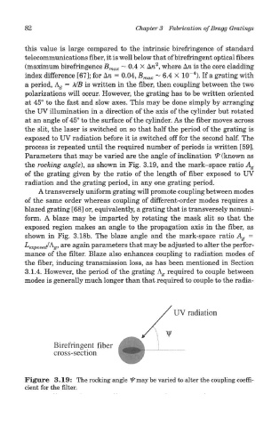
Parameters that may be varied are the angle of inclination & (known as
the rocking angle), as shown in Fig. 3.19, and the mark-space ratio A g
of the grating given by the ratio of the length of fiber exposed to UV
radiation and the grating period, in any one grating period.
A transversely uniform grating will promote coupling between modes
of the same order whereas coupling of different-order modes requires a
blazed grating [681 or, equivalently, a grating that is transversely nonuni-
form. A blaze may be imparted by rotating the mask slit so that the
exposed region makes an angle to the propagation axis in the fiber, as
shown in Fig. 3.18b. The blaze angle and the mark-space ratio A g =
L exposed/A. g, are again parameters that may be adjusted to alter the perfor-
mance of the filter. Blaze also enhances coupling to radiation modes of
the fiber, inducing transmission loss, as has been mentioned in Section
3.1.4. However, the period of the grating A^ required to couple between
modes is generally much longer than that required to couple to the radia-
Figure 3.19: The rocking angle l^may be varied to alter the coupling coeffi-
cient for the filter.