
Page 108 - Fiber Bragg Gratings
P. 108
3.1 Methods for fiber Bragg grating fabrication 87
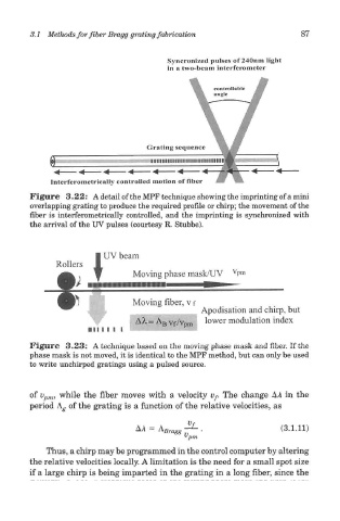
Figure 3.22: A detail of the MPF technique showing the imprinting of a mini
overlapping grating to produce the required profile or chirp; the movement of the
fiber is interferometrically controlled, and the imprinting is synchronized with
the arrival of the UV pulses (courtesy R. Stubbe).
Figure 3.23: A technique based on the moving phase mask and fiber. If the
phase mask is not moved, it is identical to the MPF method, but can only be used
to write unchirped gratings using a pulsed source.
of v pm, while the fiber moves with a velocity ty. The change A A in the
period A^ of the grating is a function of the relative velocities, as
Thus, a chirp may be programmed in the control computer by altering
the relative velocities locally. A limitation is the need for a small spot size
if a large chirp is being imparted in the grating in a long fiber, since the