
Page 114 - Fiber Bragg Gratings
P. 114
3.1 Methods for fiber Bragg grating fabrication 93
radiation to a longer wavelength. The effect of the shift is a slightly
broader overall reflection spectrum.
The use of an amplitude mask in conjunction with a phase mask
allows the precise printing of a superstructure grating [93]. Of course,
mini-gratings may be printed by precise translation of the fiber between
imprints [91,73]. This method has been used to write a sine function
grating with remarkably good results. However, it is difficult to write a
continuous sine function. Approximating the sine function in a limited
number of steps creates additional side bands, which limits the out-of-
band rejection in the reflection spectrum. Combing the sine function grat-
ing with apodization results in an improved transfer function, increasing
the depth of the out-of-band rejection [91].
Chirped gratings are useful for many applications. There are a num-
ber of ways of chirping gratings, including writing a uniform period grat-
ing in a tapered fiber [94], by application of varying strain after fabrication
[43,79,95], by straining a taper-etched fiber, by fabrication by a step-
chirped [96] or continuously chirped phase mask, or by using one of the
several schemes of writing a cascade of short, varying-period gratings to
build a composite, long grating. These methods for writing chirped grat-
ings are discussed in Section 3.1.14.
The properties of many of these gratings along with their applications
may be found in Chapter 6.
3.1.14 Fabrication of continuously chirped gratings
Short, continuously chirped gratings are relatively straightforward to
fabricate; longer (>50 mm) ones become more difficult. One of the simplest
methods is to bend a fiber such that a continuously changing period is
projected on it. This is shown in Figure 3.25 in which the fiber is bent
either in the fringe plane or orthogonal to it. Altering the lay of the fiber
may change the functional dependence of the period on position, so that
either linear or quadratic chirp may be imparted.
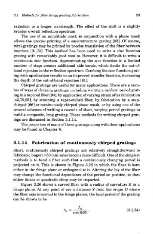
Figure 3.26 shows a curved fiber with a radius of curvature R in a
fringe plane. At any point of arc a distance S from the origin O where
the fiber axis is normal to the fringe planes, the local period of the grating
can be shown to be