
Page 185 - Fiber Bragg Gratings
P. 185
162 Chapter 4 Theory of Fiber Bragg Gratings
issue of phase matching. The grating inclination angle is 6 g with respect to
the transverse axis, x, in thex-z plane. The refractive index perturbation of
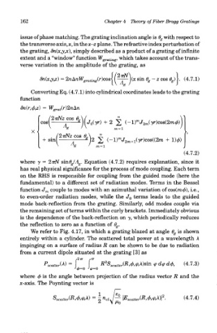
the grating, 8n(x,y,x), simply described as a product of a grating of infinite
extent and a "window" function Wgj. atilig, which takes account of the trans-
verse variation in the amplitude of the grating, as
Converting Eq. (4.7.1) into cylindrical coordinates leads to the grating
function
where y = 27rN sm6g!A g. Equation (4.7.2) requires explanation, since it
has real physical significance for the process of mode coupling. Each term
on the RHS is responsible for coupling from the guided mode (here the
fundamental) to a different set of radiation modes. Terms in the Bessel
function J m couple to modes with an azimuthal variation of cos(ra0), i.e.,
to even-order radiation modes, while the J 0 terms leads to the guided
mode back-reflection from the grating. Similarly, odd modes couple via
the remaining set of terms within the curly brackets. Immediately obvious
is the dependence of the back-reflection on y, which periodically reduces
the reflection to zero as a function of 6 g.
We refer to Fig. 4.17, in which a grating blazed at angle 0 g is shown
entirely within a cylinder. The scattered total power at a wavelength A
impinging on a surface of radius R can be shown to be due to radiation
from a current dipole situated at the grating [3] as
o — —
where (f> is the angle between projection of the radius vector R and the
x-axis. The Povnting vector is