
Page 182 - Fiber Bragg Gratings
P. 182
4.7 Radiation mode couplers 159
rapidly away from the guided mode. For a coherent interaction, the fields
must overlap over a distance with the correct phases. While the phases
may remain synchronous, the radiated field spreads away, reducing the
overlap as a function of propagation distance. With the cladding present,
the field forms a mode, which propagates in the cladding and is then
strongly coupled to the guided mode. This type of coupling is similar to
simple Bragg reflection to discrete modes of the cladding. The transmis-
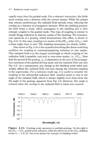
sion spectrum of a grating, which demonstrates this effect, is shown in
Fig. 4.15. In this case, coupling is to modes of the HE ln order (LP 0n), with
a blaze angle close to zero. The cladding resonances are clearly visible.
Also shown in Fig. 4.14 is the equation describing the phase-matching
condition for coupling to counterpropagating radiation at zero angles.
This radiated field is at the longest wavelength at which coupling to the
radiation field is possible, and only to zero-order modes, i.e., LP 0m. Note
that the period of the grating, A g, is dependent on the sum of the propaga-
tion constants of the guided driving mode and the radiated field (see also
Fig. 4.5). As a consequence, any change in the cladding mode index only
weakly affects the radiated field, but does change the coherent coupling
to the supermodes. For a radiation mode tap, it is useful to consider the
coupling to the unbounded radiation field. Another point to note is the
angle of the radiated field, which is always slightly more than twice the
tilt angle of the grating, apparent from Fig. 4.6. However, this angle is
reduced when the overlap to the radiated field is taken into account.
Figure 4.15: Cladding mode resonance in untilted gratings. On the right is
the LP 0i —> LP 01 guided mode reflection, while the others are to the LP Qn cladding
modes (n = 2 to 10). See cover picture for example of cladding modes.