
Page 191 - Fiber Bragg Gratings
P. 191
168 Chapter 4 Theory of Fiber Bragg Gratings
g L is the transverse momentum of the mode, depending on the output
radiation angle of the scattered light, <p L, at a given wavelength, and is
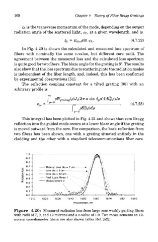
In Fig. 4.20 is shown the calculated and measured loss spectrum of
fibers with nominally the same u-value, but different core radii. The
agreement between the measured loss and the calculated loss spectrum
is quite good for two fibers. The blaze angle for the grating is 8°. The results
also show that the loss spectrum due to scattering into the radiation modes
is independent of the fiber length, and, indeed, this has been confirmed
by experimental observations [51].
The reflection coupling constant for a tilted grating [38] with an
arbitrary profile is
This integral has been plotted in Fig. 4.21 and shows that zero Bragg
reflection into the guided mode occurs at a lower blaze angle if the grating
is moved outward from the core. For comparison, the back reflection from
two fibers has been shown, one with a grating situated entirely in the
cladding and the other with a standard telecommunications fiber core.
Figure 4.20: Measured radiation loss from large core weakly guiding fibers
with radii of 7, 9, and 12 microns and a u-value of 1.9. Two measurements on 12-
micron core-diameter fibers are also shown (after Ref. [52]).