
Page 193 - Fiber Bragg Gratings
P. 193
170 Chapter 4 Theory of Fiber Bragg Gratings
Figure 4.22: The loss spectrum (calculated and measured) for a photosensi-
tive cladding fiber. The ripple in the loss spectra is a measurement artifact (after
Ref. [52]).
rise to a sharp narrow-bandwidth peak. Above 6.5°, the coupling is to odd-
azimuthal order modes and becomes much broader. By making angles for
the back-reflection small (Fig. 4.21), one benefits from both low polariza-
tion sensitivity and a narrow-loss spectrum.
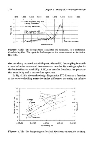
In Fig. 4.23 is shown the design diagram for STG filters as a function
of the core-to-cladding refractive index difference, assuming an infinite
Figure 4.23: The design diagram for tilted STG filters with infinite cladding.