
Page 197 - Fiber Bragg Gratings
P. 197
174 Chapter 4 Theory of Fiber Bragg Gratings
above the initial mismatch, A/6 between the modes, and 17 is the overlap
of the field within the core. A comparison between the two leads to
In Eq. (4.7.27) the average effective index has been replaced by n core
and the difference in the mode propagation constants by the core-to-
cladding index difference. Therefore, for a typical fiber, the LPG is between
— XlOO and XlOOO more sensitive than the STG to the changes between
the propagation constants of the core and the cladding modes.
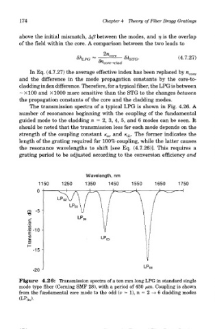
The transmission spectra of a typical LPG is shown in Fig. 4.26. A
number of resonances beginning with the coupling of the fundamental
guided mode to the cladding n = 2, 3, 4, 5, and 6 modes can be seen. It
should be noted that the transmission loss for each mode depends on the
strength of the coupling constant K ac and K dc. The former indicates the
length of the grating required for 100% coupling, while the latter causes
the resonance wavelengths to shift [see Eq. (4.7.26)]. This requires a
grating period to be adjusted according to the conversion efficiency and
Figure 4.26: Transmission spectra of a ten mm long LPG in standard single
mode type fiber (Corning SMF 28), with a period of 450 /mi. Coupling is shown
from the fundamental core mode to the odd (u = l), n = 2—» 6 cladding modes
(LP 0J.