
Page 252 - Fiber Bragg Gratings
P. 252
6.1 Distributed feedback, Fabry-Perot, superstructure, and moire gratings 229
erating wavelength is only ~2 nm. As a fraction of the channel spacing
(100 GHz or 0.8 nm), it is still too large and must be stabilized. Thus,
schemes need to be developed to counter the effects of temperature. Pas-
sive packaging can isolate the grating from experiencing effects of strain.
Both temperature and strain have been used along with grating-based
band-pass filters to control novel functions such as optical add-drop multi-
plexers and demultiplexers.
We now consider some of these filters in detail, along with their
attributes and shortcomings.
6.1 Distributed feedback, Fabry-Perot,
superstructure, and moire gratings
The general form of the band-pass filter described in this section is a
grating or a combination of gratings physically written at the same loca-
tion. The composite transmission spectrum of this band-pass filter can
be a single or a series (one to many) of high transmission windows sepa-
rated by bands that are rejected by reflection.
6.1.1 The distributed feedback grating
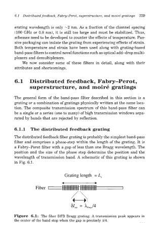
The distributed feedback fiber grating is probably the simplest band-pass
filter and comprises a phase-step within the length of the grating. It is
a Fabry-Perot filter with a gap of less than one Bragg wavelength. The
position and the size of the phase step determine the position and the
wavelength of transmission band. A schematic of this grating is shown
in Fig. 6.1.
Grating length = L
Figure 6.1: The fiber DFB Bragg grating. A transmission peak appears in
the center of the band stop when the gap is precisely A/4.