
Page 257 - Fiber Bragg Gratings
P. 257
234 Chapter 6 Fiber Grating Band-pass Filters
by Haus for semiconductor DFB structures [3,4]. Figure 6.5 shows the
practical implementation of such a grating.
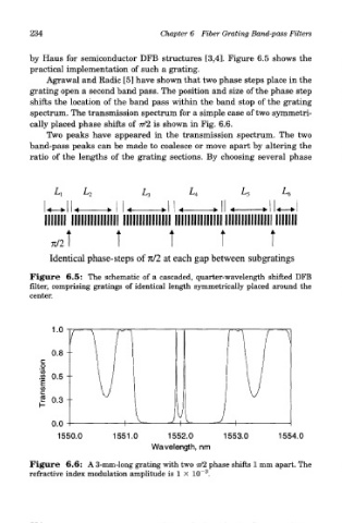
Agrawal and Radic [5] have shown that two phase steps place in the
grating open a second band pass. The position and size of the phase step
shifts the location of the band pass within the band stop of the grating
spectrum. The transmission spectrum for a simple case of two symmetri-
cally placed phase shifts of 77/2 is shown in Fig. 6.6.
Two peaks have appeared in the transmission spectrum. The two
band-pass peaks can be made to coalesce or move apart by altering the
ratio of the lengths of the grating sections. By choosing several phase
Identical phase-steps of n/2 at each gap between subgratings
Figure 6.5: The schematic of a cascaded, quarter-wavelength shifted DFB
filter, comprising gratings of identical length symmetrically placed around the
center.
Figure 6.6: A 3-mm-long grating with two 77/2 phase shifts 1 mm apart. The
3
refractive index modulation amplitude is 1 X 10~ .