
Page 258 - Fiber Bragg Gratings
P. 258
6.1 Distributed feedback, Fabry-Perot, superstructure, and moire gratings 235
shifts Zengerle and Leminger [4] demonstrated the ideal ratios of the
lengths of the gratings for an optimized pass band. A quality factor s,
defined as the ratio of the pass bandwidth at 10% and 90%, is 0.16 for a
single phase-step DFB grating with a coupling constant xL «* 2.9. A length
sequence of 1:2:2.17:2.17:2:1 appears to produce a ripple of only 0.3 dB
within the pass band with a quality factor of —0.87. This ratio of the
grating lengths will produce the quality factor irrespective of the overall
length of the grating. The design was for a semiconductor grating, and
the target was for a 0.4-nm band-pass filter. In Fig. 6.5, six gratings are
shown with intermediate phase shifts. The lengths L l = L 6 : L 2 = L 5 :
L 3 = L 4 should therefore have the ratio of 1:2:2.17. Note the flat-top pass
band.
Wei and Lit [12] have examined symmetrical configurations of 3 and
4 phase-shifted structures. Unity transmission occurs for a symmetrical
three-grating-section filter with two 77/2 phase shifts when the grating at
either end is half the length of the grating(s) in between. Although this
is not a unique condition for unity transmission at the Bragg wavelength
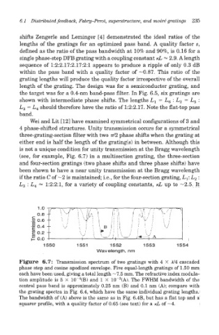
(see, for example, Fig. 6.7) in a multisection grating, the three-section
and four-section gratings (two phase shifts and three phase shifts) have
been shown to have a near unity transmission at the Bragg wavelength
if the ratio C of ~2 is maintained; i.e., for the four-section grating, L T: L 2 :
L 3 : L 4 «= 1:2:2:1, for a variety of coupling constants, /cL up to —2.5. It
Figure 6.7: Transmission spectrum of two gratings with 4 X A/4 cascaded
phase step and cosine apodized envelope. Five equal-length gratings of 1.50 mm
each have been used, giving a total length —7.5 mm. The refractive index modula-
4
3
tion amplitude is 5 X 10~ (B) and 1 X 10~ (A). The FWHM bandwidth of the
central pass band is approximately 0.25 nm (B) and 0.1 nm (A); compare with
the grating spectra in Fig. 6.4, which have the same individual grating lengths.
The bandwidth of (A) above is the same as in Fig. 6.4B, but has a flat top and a
squarer profile, with a quality factor of 0.65 (see text) for a /cL of —4.