
Page 263 - Fiber Bragg Gratings
P. 263
240 Chapter 6 Fiber Grating Band-pass Filters
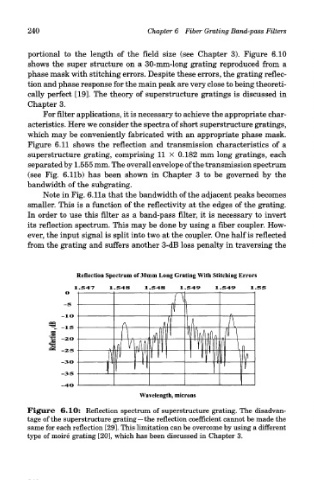
portional to the length of the field size (see Chapter 3). Figure 6.10
shows the super structure on a 30-mm-long grating reproduced from a
phase mask with stitching errors. Despite these errors, the grating reflec-
tion and phase response for the main peak are very close to being theoreti-
cally perfect [19]. The theory of superstructure gratings is discussed in
Chapter 3.
For filter applications, it is necessary to achieve the appropriate char-
acteristics. Here we consider the spectra of short superstructure gratings,
which may be conveniently fabricated with an appropriate phase mask.
Figure 6.11 shows the reflection and transmission characteristics of a
superstructure grating, comprising 11 X 0.182 mm long gratings, each
separated by 1.555 mm. The overall envelope of the transmission spectrum
(see Fig. 6.lib) has been shown in Chapter 3 to be governed by the
bandwidth of the subgrating.
Note in Fig. 6.11a that the bandwidth of the adjacent peaks becomes
smaller. This is a function of the reflectivity at the edges of the grating.
In order to use this filter as a band-pass filter, it is necessary to invert
its reflection spectrum. This may be done by using a fiber coupler. How-
ever, the input signal is split into two at the coupler. One half is reflected
from the grating and suffers another 3-dB loss penalty in traversing the
Figure 6.10: Reflection spectrum of superstructure grating. The disadvan-
tage of the superstructure grating—the reflection coefficient cannot be made the
same for each reflection [29]. This limitation can be overcome by using a different
type of moire grating [20], which has been discussed in Chapter 3.